
Power Monitoring at Critical Sites: UPS, Batteries, Rectifiers and Generators in One View
Power monitoring at a critical site covers the whole chain: utility, transfer switch, generator, UPS or rectifier, and the batteries behind them. The most important lesson is that a UPS can show OK while its batteries have lost most of their capacity, so batteries must be checked block by block and their runtime measured under real load at least once a year.
In this article
- What does power monitoring cover at a critical site?
- What to measure on each element
- Why a UPS can show OK and still fail
- UPS and battery inspection checklist
- Battery limits worth knowing
- Telecom sites: rectifiers and 48 V batteries
- How to bring power monitoring into one view
- Frequently asked questions
- Sources
When the power fails at a shop, an office or a telecom site, it is rarely one component that lets the site down. It is the chain: the utility goes, the transfer switch moves, the generator starts, and for the seconds or hours in between, a UPS or a battery string carries the load. If one link has quietly failed, the outage is where you find out.
Power monitoring is the practice of watching that whole chain, so the weak link is found on a normal working day instead.
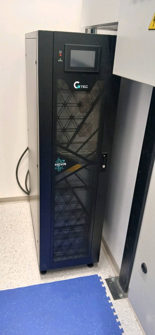
What does power monitoring cover at a critical site?
A complete power monitoring setup reads every element between the grid and the load:
- Utility supply: voltage and frequency on each phase, outages and their length.
- Transfer switch: which source feeds the load and how long each transfer took.
- Generator: status, alarms, fuel, run hours and test results.
- UPS at AC sites such as shops, offices and data rooms: input and output, load, bypass status and alarms.
- Rectifier at telecom sites: DC output voltage, module status and load current.
- Batteries: behind the UPS or on the 48 V DC bus, the part that most often fails without warning.
- Environment: room temperature, which decides how long the batteries live.
What to measure on each element
| Element | Key measurements | Typical alarm |
|---|---|---|
| Utility | Voltage and frequency per phase | Outage, under or over voltage |
| Transfer switch | Source position, transfer time | Failed or slow transfer |
| Generator | Mode, alarms, fuel level, battery voltage, run hours | Not in AUTO, failed start, low fuel |
| UPS | Input and output voltage, load %, bypass, battery runtime | On battery, on bypass, overload, battery fault |
| Rectifier | DC voltage, load current, module status | Module failure, mains failure, high or low DC voltage |
| Batteries | String voltage, block voltages, current, temperature | Low voltage, high temperature, discharge |
| Room | Temperature, sometimes humidity | Temperature above the limit |
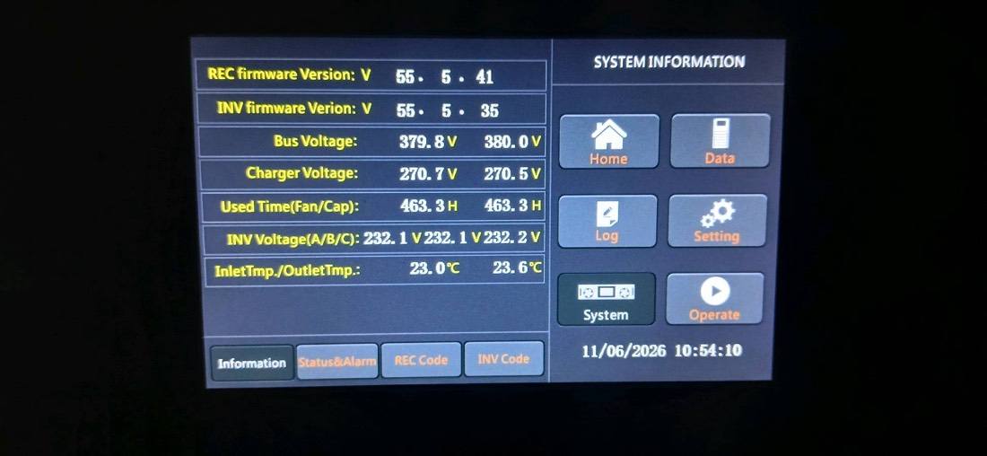
UPS systems and rectifier controllers usually report over SNMP or Modbus, and generators through their controller. A monitoring platform that reads all of them can put an outage on one timeline: utility lost, UPS on battery, generator started, load transferred, utility back.
Why a UPS can show OK and still fail
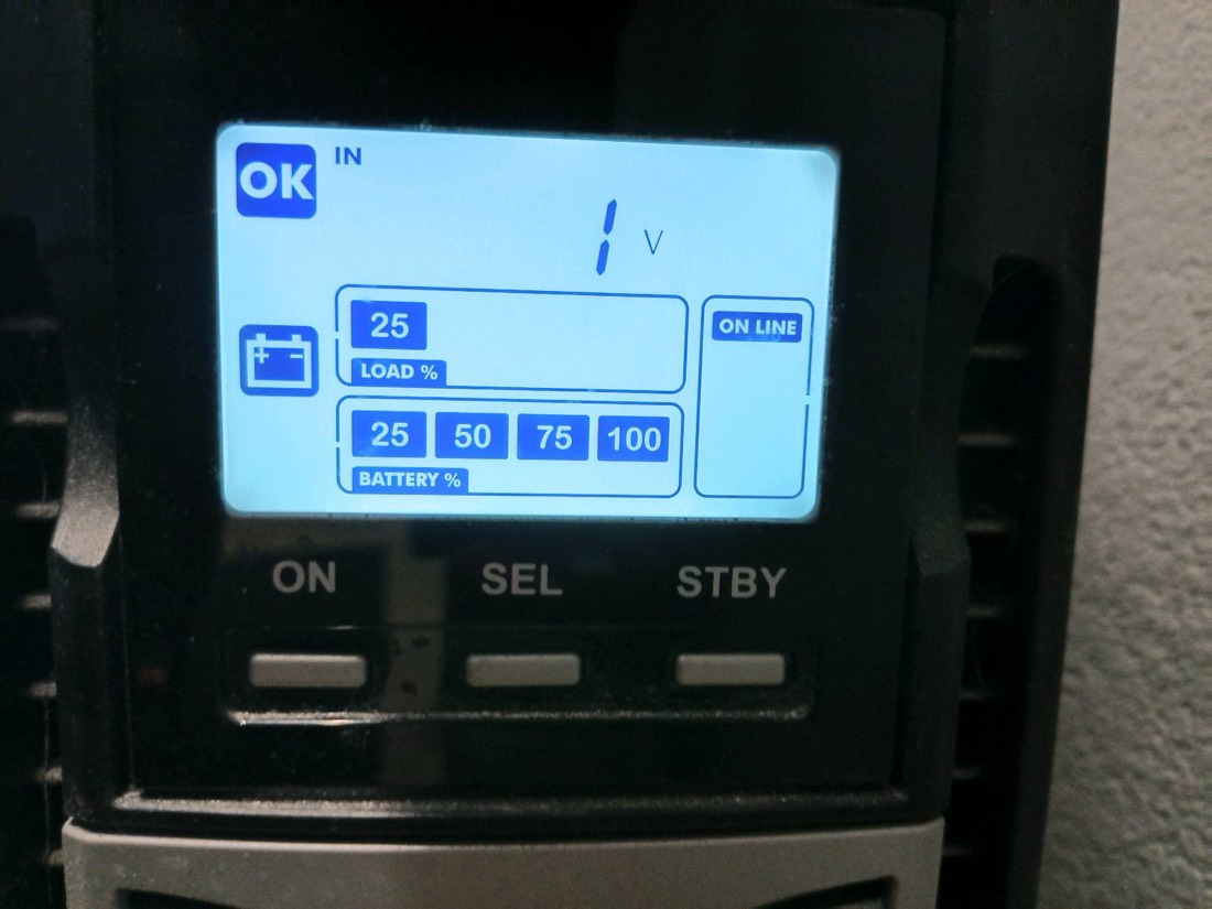
A UPS display reports what it can measure, mostly voltages. A battery string can hold a normal voltage while it is resting on charge and still have lost most of its capacity. The weakness only shows when the batteries have to deliver current, which is exactly the moment of a real outage.
That is why a UPS inspection has two tasks that matter more than everything else:
- Measure the runtime under real load. Simulate a supply failure, with the site's approval and with critical loads protected, and time how long the UPS carries the load until the low battery alarm. Compare it with the declared runtime.
- Measure every battery block. One weak block limits the whole string, and the string voltage hides it.
UPS and battery inspection checklist
A routine inspection, once a year at minimum, covers twelve checks:
- Display, status and alarm log. No active alarms; read and record the alarm history to see whether the UPS has already switched to battery or reported a battery fault. Check the clock.
- Runtime test under load. Simulate a supply failure and time the runtime to the low battery alarm under real load.
- Battery block voltages. Measure and record each block on float.
- Battery age. Record the installation date from the label, and fit a label if there is none.
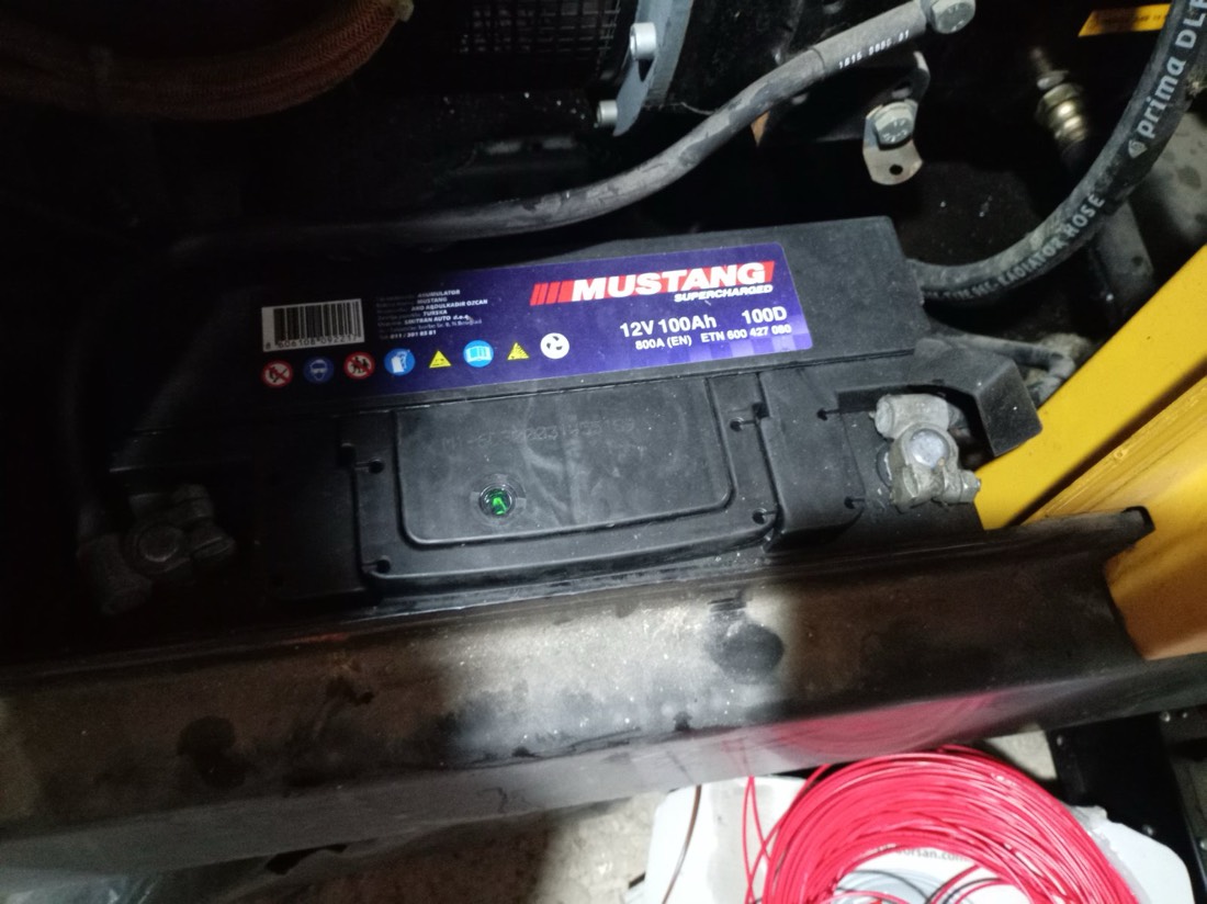
- Physical condition of the batteries. No swelling, deformation, leaks or smell; terminals free of corrosion; links tight. A swollen battery is taken out of service immediately.
- Load and connected equipment. Record the load in %; check that nothing unplanned such as heaters or chargers is connected to the UPS output.
- Ventilation, filters and dust. Vents open, filters and heat sinks clean, fans running without unusual noise, nothing stored against the unit.
- Room temperature. Measure and record it.
- Input, output and bypass. Voltages and frequency within limits; transfer to bypass and back without interrupting the load.
- Electrical connections and earthing. Terminals tight, no signs of overheating, earth connected, fuses and breakers correct and labelled.
- Emergency power off (EPO). Button present, labelled and protected against accidental use; functional tests only by plan and with approval.
- Surroundings and fire protection. Extinguisher nearby and in date, no combustible material around the UPS, signs and instructions in place.
Battery limits worth knowing
These are the reference values our field teams work with. Always check them against the battery manufacturer's data for the specific model.
| Parameter | Reference value | What it means |
|---|---|---|
| 12 V block voltage on float | About 13.5 to 13.8 V | 2.25 to 2.30 V per cell at 20 to 25 °C |
| Block deviation from the others | More than 0.5 V | Suspicious block; investigate |
| Block voltage | Below 12.5 V | Replace the block |
| Internal resistance | More than 20% above the initial value | Replace; needs a baseline measurement (IEEE 1188) |
| Measured runtime | Below 50% of the declared runtime | Replace the batteries |
| Capacity | Below 80% of rated | End of service life |
| VRLA battery age | 3 to 5 years typical | Plan replacement after 5 years regardless of test results |
| UPS load | Up to about 80% of rating | Headroom for runtime and transients |
| Room temperature | 20 to 25 °C | Every 10 °C above 25 °C roughly halves battery life |
Telecom sites: rectifiers and 48 V batteries
At telecom sites the critical load usually runs on DC. A rectifier system converts mains or generator power to around 48 V nominal DC, feeds the radio and transmission equipment and keeps a battery string on float charge. When the supply fails, the batteries carry the site until the generator starts or the mains returns.
The same lessons apply: monitor the DC bus voltage and the battery current, alarm on mains failure and on battery discharge, and know how long the batteries can actually hold the site. If the generator fails to start, the battery runtime is the time the field team has to get there.
How to bring power monitoring into one view
- Connect every device that can report. UPS systems and rectifier controllers over SNMP or Modbus, generators through their controllers, and simple dry contacts where nothing else exists.
- Use one alarm list and one timeline per site, so an outage shows as one event chain rather than ten unrelated alarms.
- Record inspection results in the same place: runtime tests, block voltages, battery age and room temperature, so trends become visible from year to year.
- Plan battery replacement from data: age, measured runtime and weak blocks, not only the calendar.
Frequently asked questions
What is power monitoring?
Power monitoring is the continuous measurement of the electrical supply and backup equipment at a site: utility supply, transfer switch, generator, UPS or rectifier, batteries and room temperature, with alarms when something goes outside its limits.
How often should a UPS be serviced?
A UPS should have a full inspection at least once a year, including a runtime test under load and a block by block battery measurement. Critical sites often add more frequent visual checks and continuous remote monitoring.
How long do UPS batteries last?
VRLA batteries commonly used in UPS systems typically last 3 to 5 years in service, less in warm rooms. A common rule of thumb is that every 10 °C above 25 °C halves the expected battery life.
How do you test UPS batteries?
Measure each battery block voltage on float, check physical condition and connections, and run a runtime test by simulating a supply failure under real load. Compare the measured runtime with the declared runtime; below 50% means the batteries need replacing.
What is the float voltage of a 12 V battery in a UPS?
For VRLA batteries the float voltage of a 12 V block is typically about 13.5 to 13.8 V, or 2.25 to 2.30 V per cell at 20 to 25 °C. Always use the value specified by the battery manufacturer.
Sources
- IEEE 1188, Recommended Practice for Maintenance, Testing, and Replacement of Valve-Regulated Lead-Acid (VRLA) Batteries for Stationary Applications.
- UPS, rectifier and battery manufacturers' operation and maintenance documentation.
- Domar field procedure for UPS inspection (batteries, runtime test, cleaning).
- Related reading: remote generator monitoring and ATS testing and maintenance.

See every generator's status and service plan in one place
GenSetCare reads alarms, fuel and run hours from the controller, schedules service by run hours and calendar, and gives technicians a field app with live checklists.